Sample Work
Induction Furnace
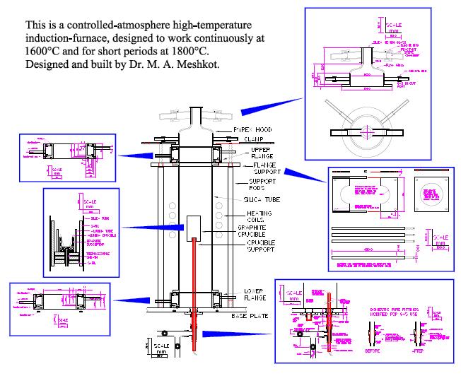
Unique Design of an Induction Furnace Designed and Built to Work at 1600°C.
Dr. M. A. Meshkot
March 1991
The induction furnace is basically an elaborate heating chamber with a an induction heating coil around it. The water-cooled coil is connected to a high frequency generator to produce heat in a susceptor within the chamber by induced current.
The heating chamber in this case is a silica tube of 100 mm ID and 400 mm height with a water-cooled flange at each end. The heating coil is placed central and external to this tube. Below the lower flange is a base plate mounted on a trolley and above the upper flange is a Pyrex hood containing a viewing port, two gas ports and two reactant ports. One of the gas ports is connected to a manometer and the other is used to carry away exhaust gases.
Above the Pyrex hood is a split plate which can be set to exert a downward force on the hood in case experiments need to be done at positive pressures. The weight of the upper flange is supported by a platform which is held up using four support rods around the chamber and rising from the base plate. The same rods pass through the split plate for a compressive action.
Gas input and vacuum facilities are housed below the base plate. Originally high accuracy manostats and regulators were designed for use with this furnace, but a calibrated rotameter was found to give adequate accuracy. A needle valve controls the gas input rate and the chamber may be evacuated from below if required. A further port through the base plate is included as spare. This apparatus includes a gas mixing facility housed on the same trolley and separated from the heating chamber by an aluminium plate.
The furnace is designed to withstand a temperature of 1800 °C with a working temperature of 1600 °C. The water-cooled cylindrical flanges were designed with safety in mind and their design is such that they contain no soldered parts which could come apart if there was over-heating. Also there is no direct groove or joint through which water could leak into the heating chamber. A cross-section of the lower flange and the upper one is shown in the PDF file of this design. The two flanges are similar except for the base plate connections to the lower flange which slightly alter the shape of the water chamber.
The temperature was measured by means of a Pt/Pt-13%Rh thermocouple protected by a close-ended alumina rod and protruding from under the crucible platform. The thermocouple rod is introduced into the chamber through a gas tight connector at the centre of the base plate. The temperature is controlled by means of the coil current generator controls.
Gas pipe connections to the base plate and underside of the chamber are made using conventional domestic plumbing connectors for copper pipes. The connectors were modified for gas use by replacing the normal olive with a specially made olive and a rubber o-ring to make them impermeable and gas tight.
Please click on the link below to return to the English Home Page
If you require some further information, Please Contact Me
Copyright © 1991 Dr. M. A. Meshkot
This page was last updated May 2004